(for higher resolution photos visit: Zhixy’s Gallery)
Next up… I’ve added a ACA1233n accelerator daughterboard.
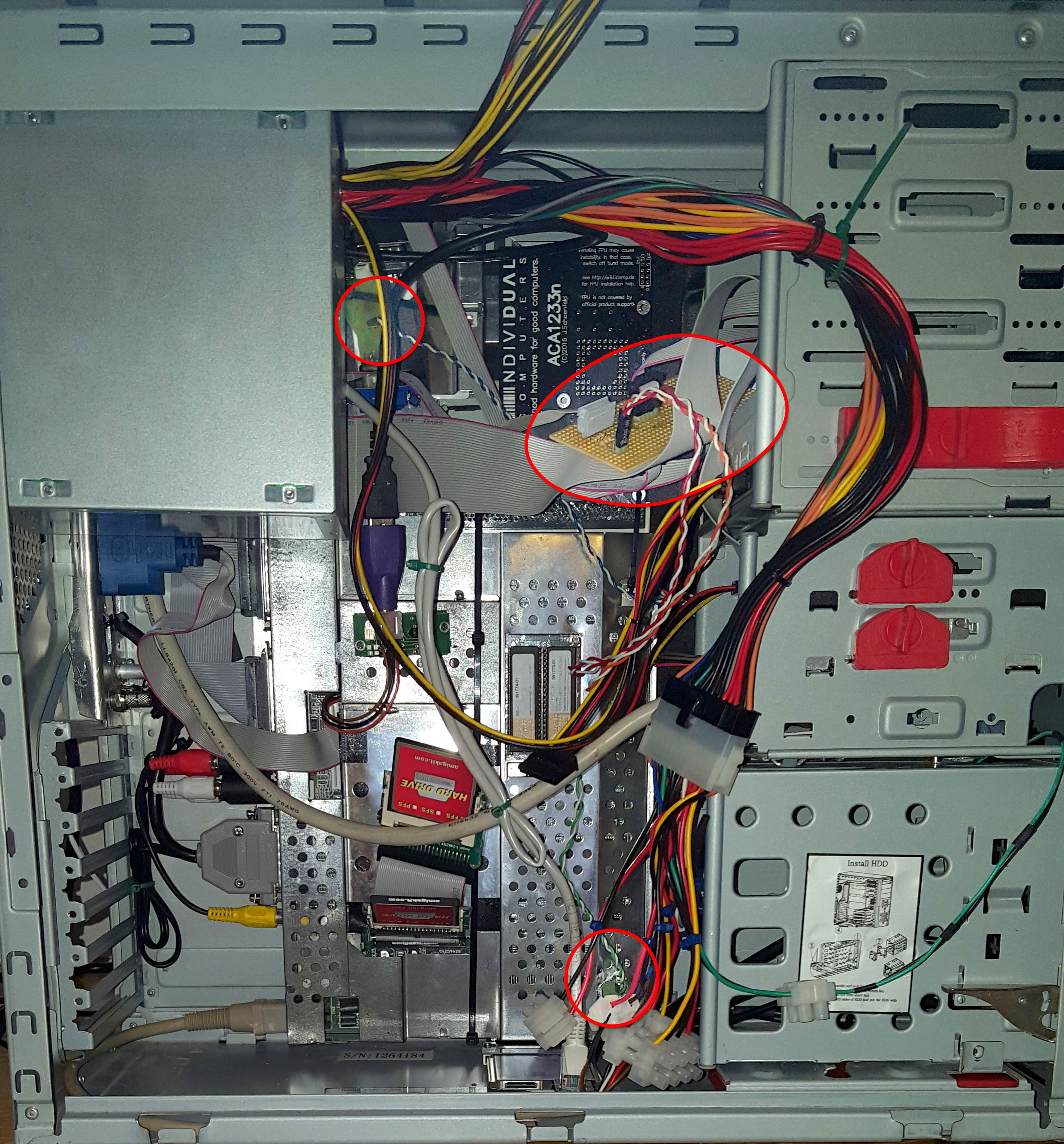 The top-left circle… that’s a modified Jerry+ Joystick adaptor which splits joystick port 1 into a PS/2 compatible USB mouse and… well a joystick in port 1. I have replaced the LED with a jumper so I can connect it to one of the LEDs at the front.
The circle at the bottom is where I’ve added a jumper on the motherboard for the reset switch.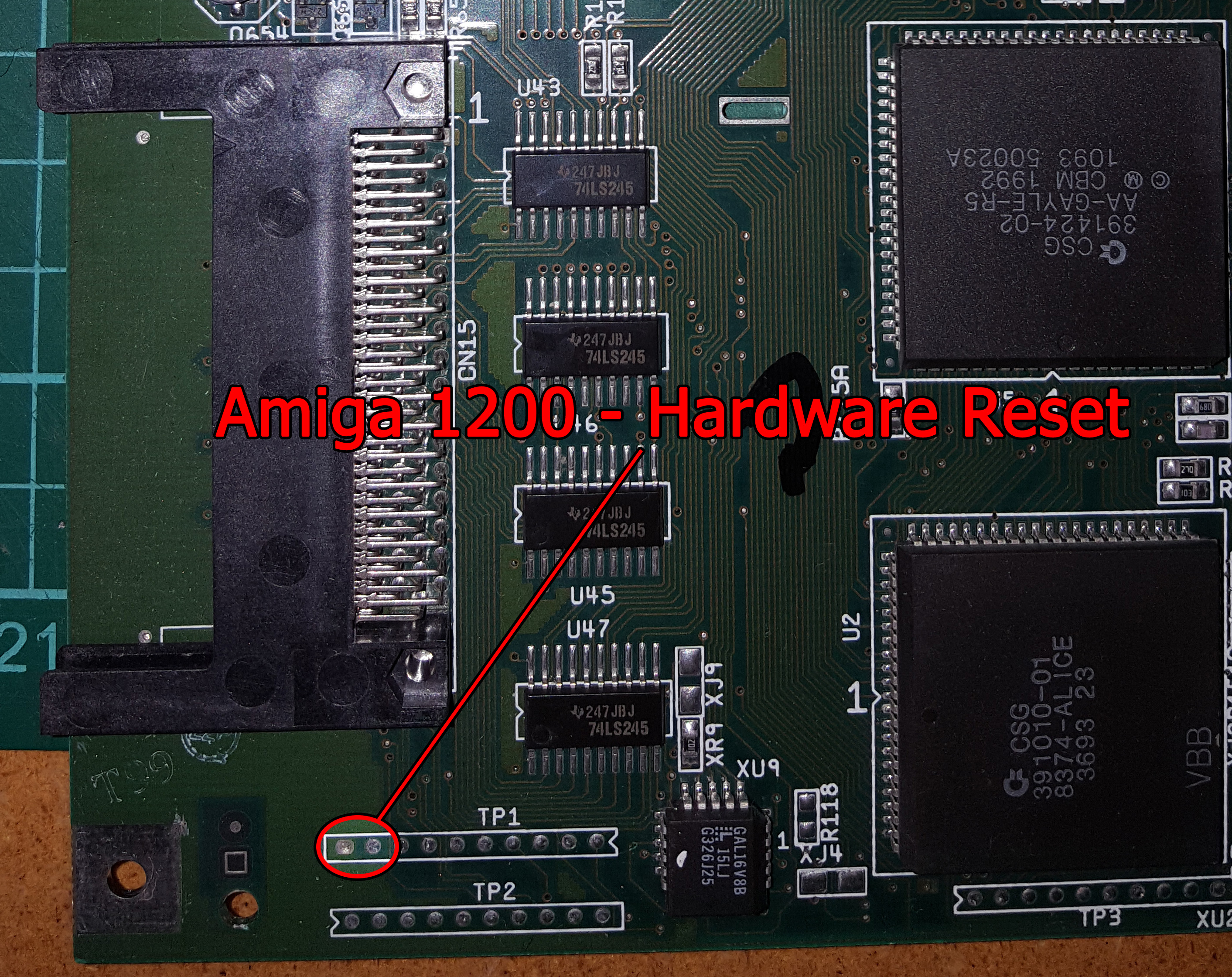
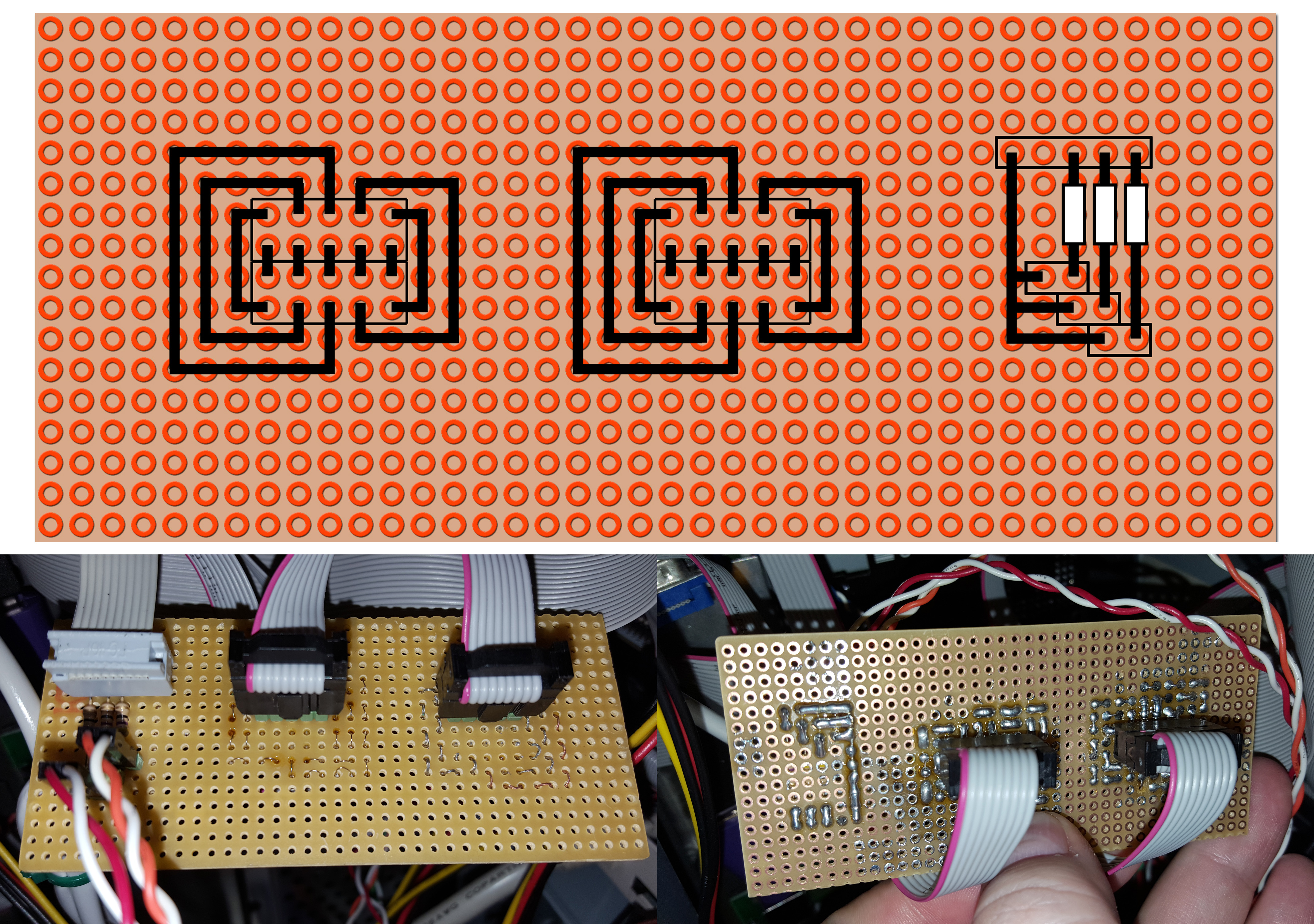 … and the remaining circle is a custom made adaptor PCB to convert the A1200 Power, HDD and floppy LED connector so I can connect them up to the LEDs in the front. Those 3 resisters are 47 Ohms.
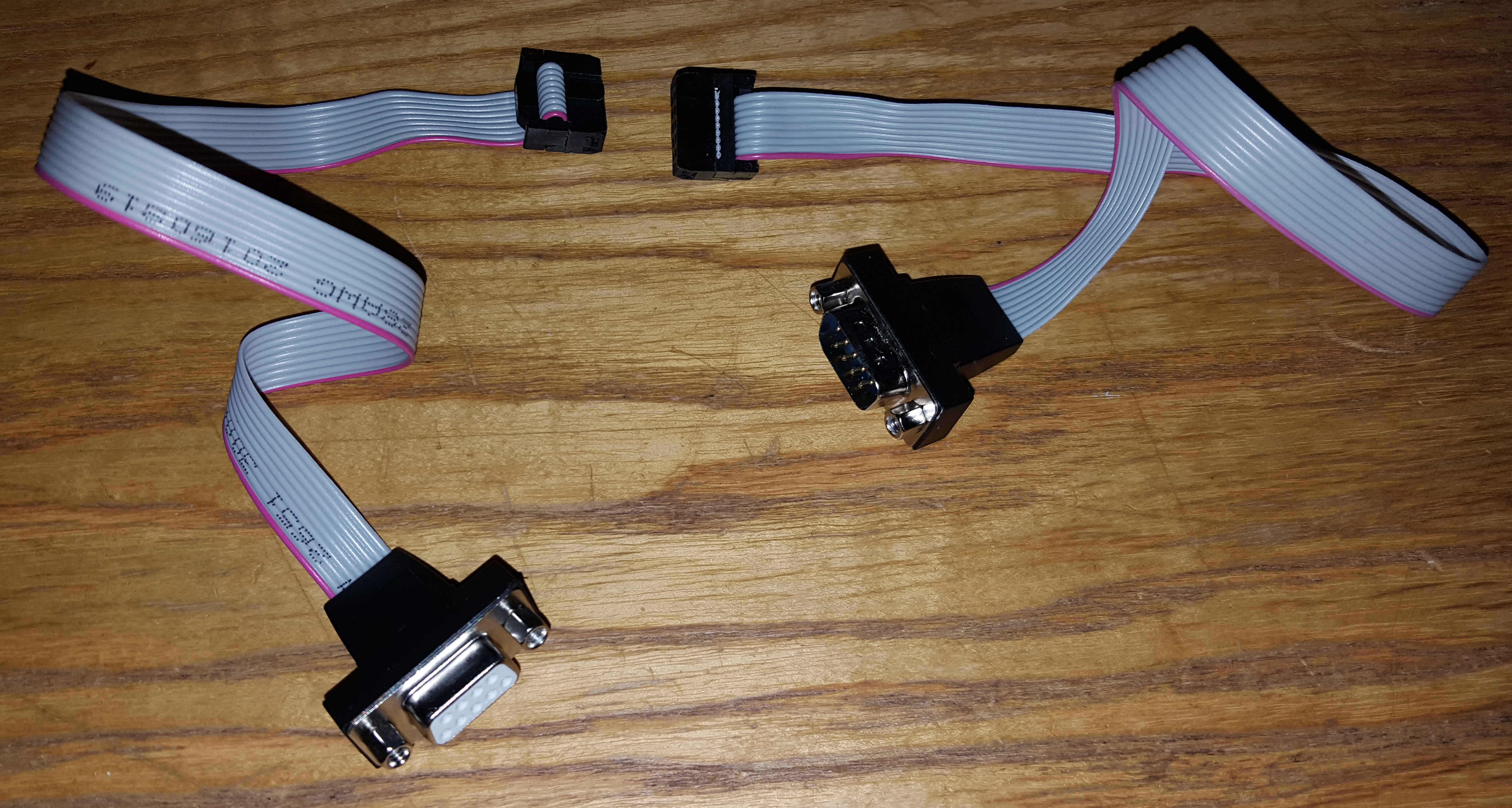 The idea of the those four 10-pin connectors is simply to link cables like above together in order to replicate joystick port 1 and 2 out to the front. The PCB will obviously need to be fastened in some way.
 Got the screen hooked up to HDMI via a DVI scan-doubler with a to-HDMI adaptor on it. I’ve had some problems trying to create the RGB-port to SCART and VGA cable. I don’t quite understand why yet, as I have made many of those cables in the past. I’ll give it some time come back to it and try again. For now I’ve just pulled a SCART cable I bought to the insides. Probably going to use the HDMI for the most part anyway.
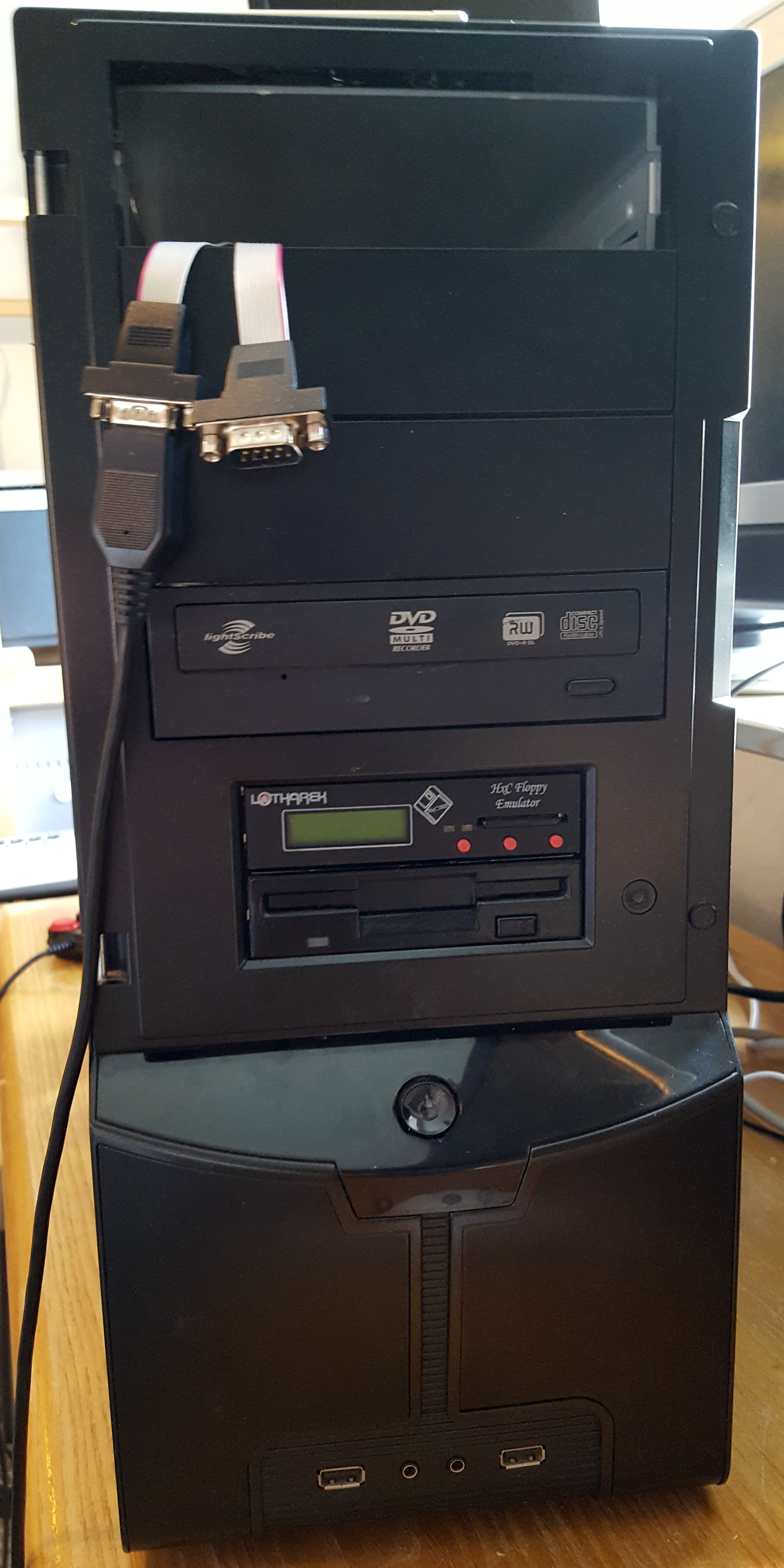 I’m still waiting for a 4 EIDE adaptor daughterboard, so I can connect up the DVD drive. But the Gotek emulator and floppy drive are hooked up and working. That is an actually Amiga external drive at the bottom (the old ones are the best). It was very yellowed and the front plastics have gotten a coat of black spray paint to match the cabinet.
Here… I did a video of my first real test run for you. Sorry about the poor sound quality. I guess I just spend more money on my retro computers than on cameras. That old second hand Prosonic TV isn’t the best either.
One thought on “Amiga 1200 Tower Project – Continued”