
Building a spare Amiga 1200 motherboard into a PC ATX Cabinet.
(for higher resolution photos visit: Zhixy’s Gallery)
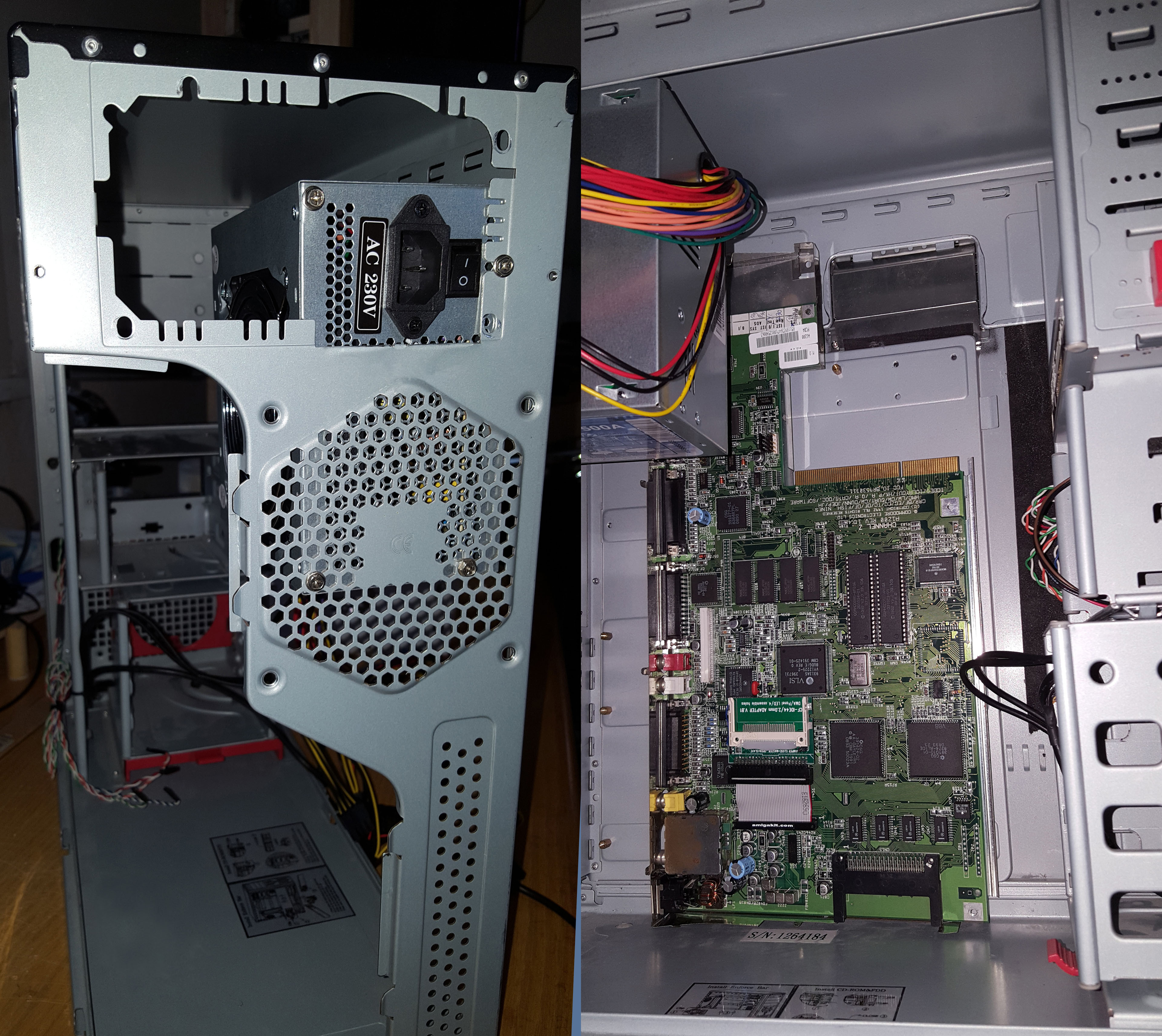 A Commodore Amiga 1200’s motherboard doesn’t just by default (and for good reasons) fit into a standard PC ATX form factor cabinet and even though I’ve found a fairly large cabinet, it still wouldn’t fit without some modifications to the cabinet.
First turning the power supply 90° and mounting it “wrongly” while still making sure can “breathe” seems to be the obvious solution to the problem.
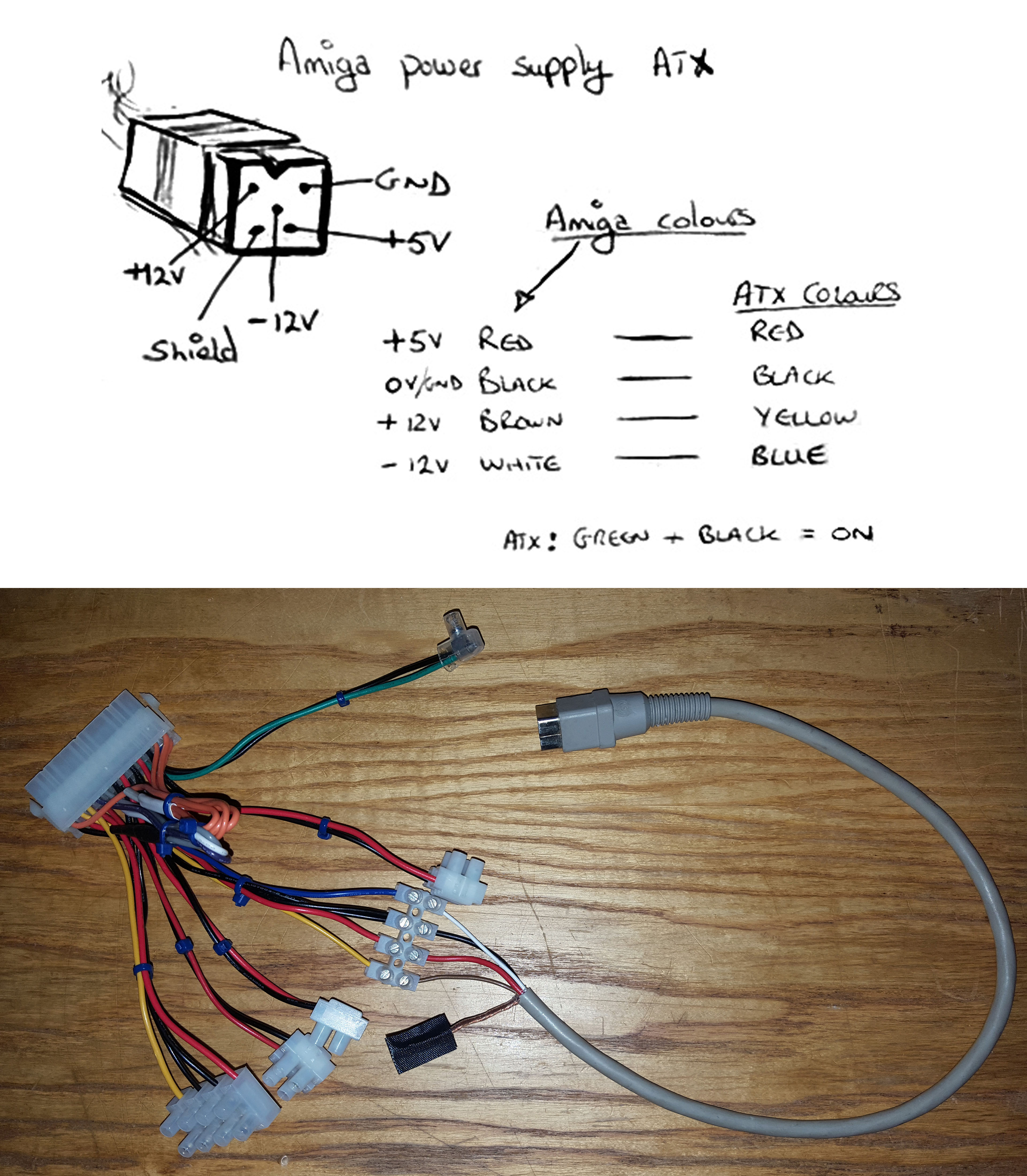 It’s not really that complicated to modify a PC’s PSU to power an Amiga 500, 600 or 1200.
But I wanted to be able to change the PSU without having to do all the modifications again so I chose to butcher an ATX adaptor cable instead. The commodore power plug actually comes from my old C128’s power supply (it had given up) which is very similar to the Amiga’s.
Notice that the green wire is shorted with one of the blacks in order to force the PSU to turn on. Later I am going to connect those two to a on/off switch on the front of the cabinet.
Thanks to MsMadLemon for your brilliant YouTube video 🙂https://youtu.be/DMxNH-PCYew
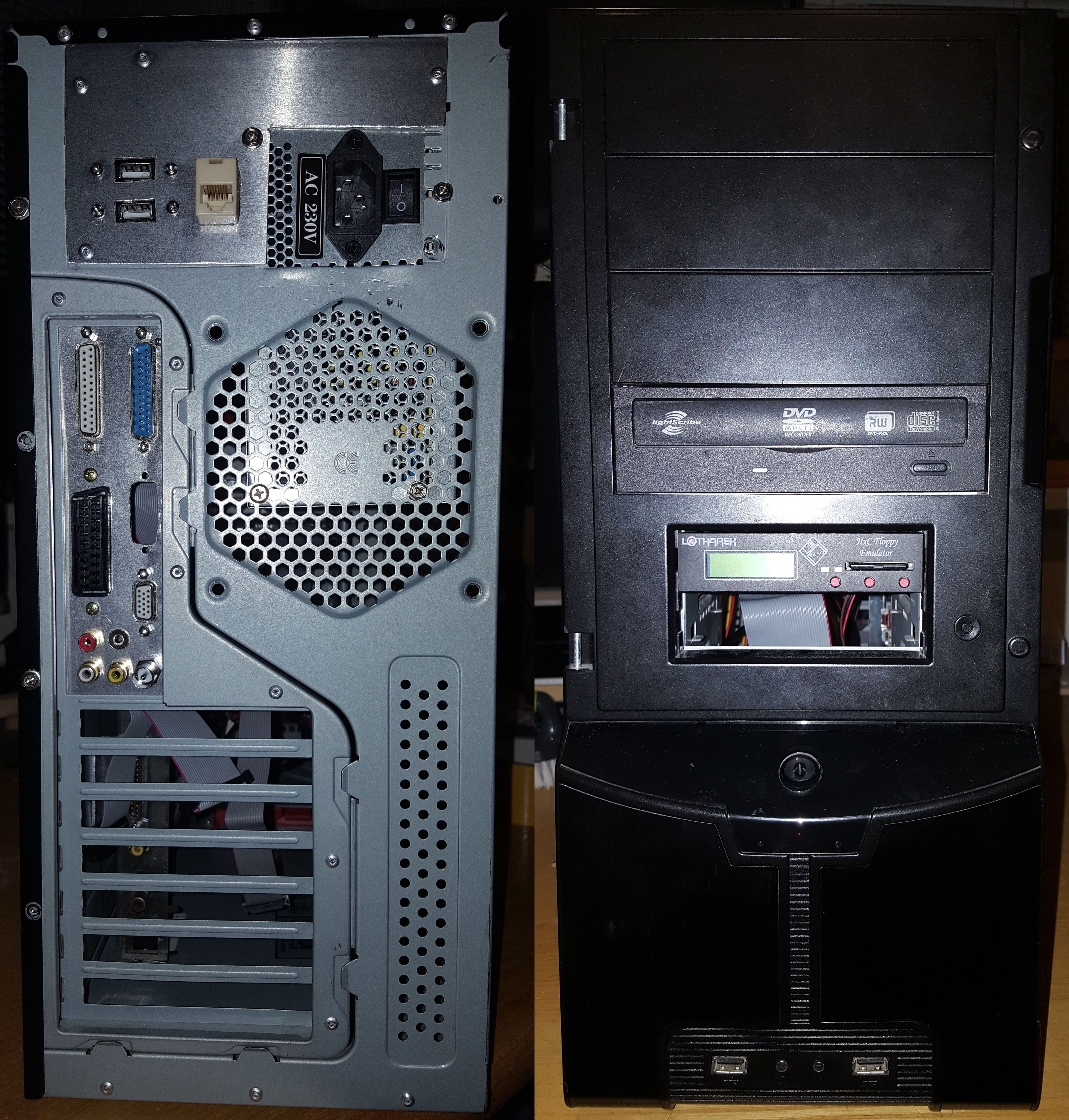
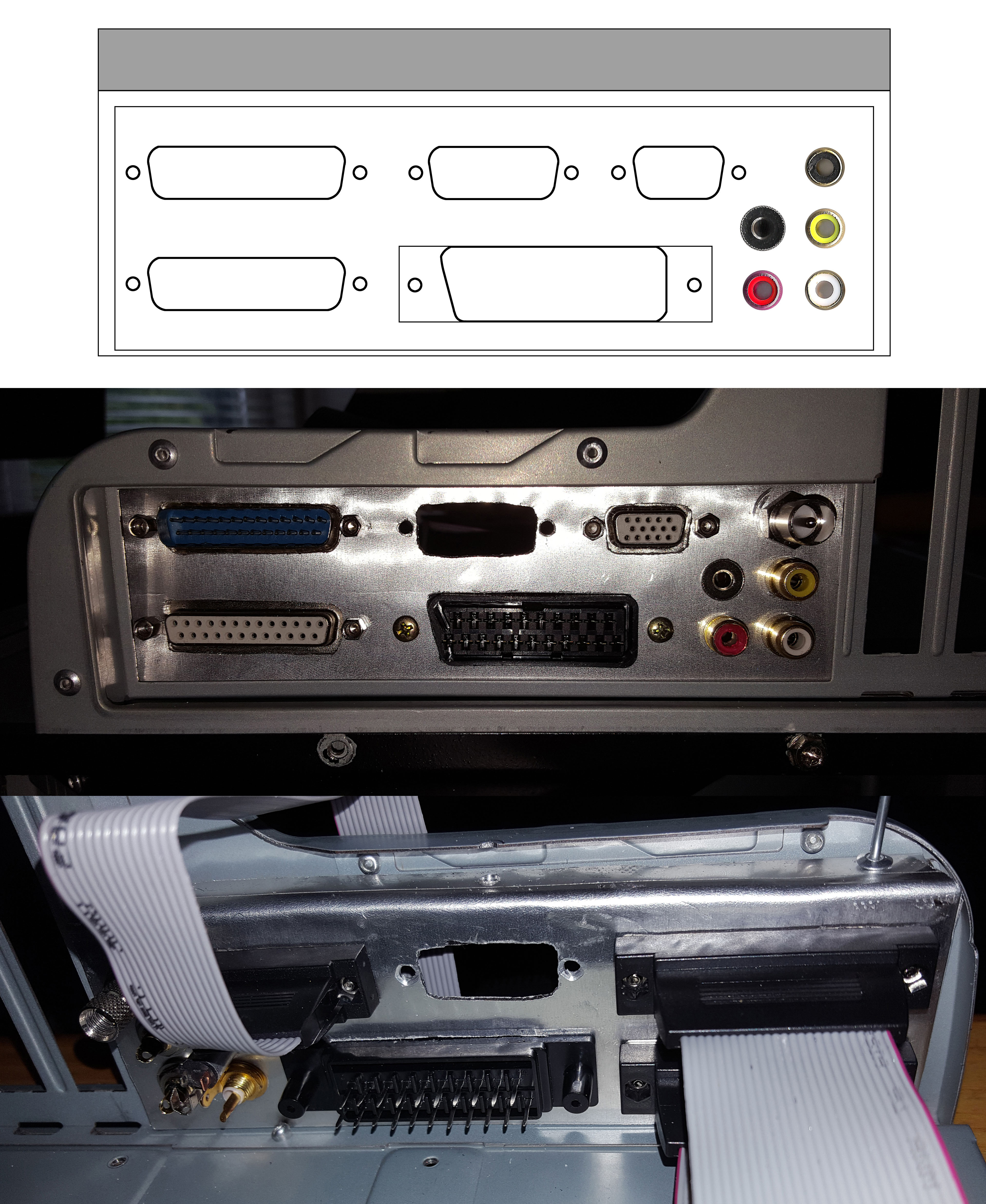 A custom made back plade was needed in order to replicate some of the A1200’s plugs out the back.
The serial and parallel ports were the easiest as I just bought some standard flat cabled plugs, cut them to size and crimped on the matching DB25 plugs.
I have a daughterboard which snaps onto the Lisa chip, giving me a digital DVI (HDMI) port. That’s what the extra hole is for.
The RGB port is going to be represented by a VGA and a SCART plug. The Audio is split into the standard RCA’s, a mini-jack and obviously the SCART plug too. The RF gets a “modern day” startard RF plug.
Any extra floppy drives are going to be mounted inside the cabinet, so the external disk drive port doesn’t need to be replicated.
I’m also going to add a PS/2 mouse splitter-converter and replicate the joystick ports to the front for easy access.
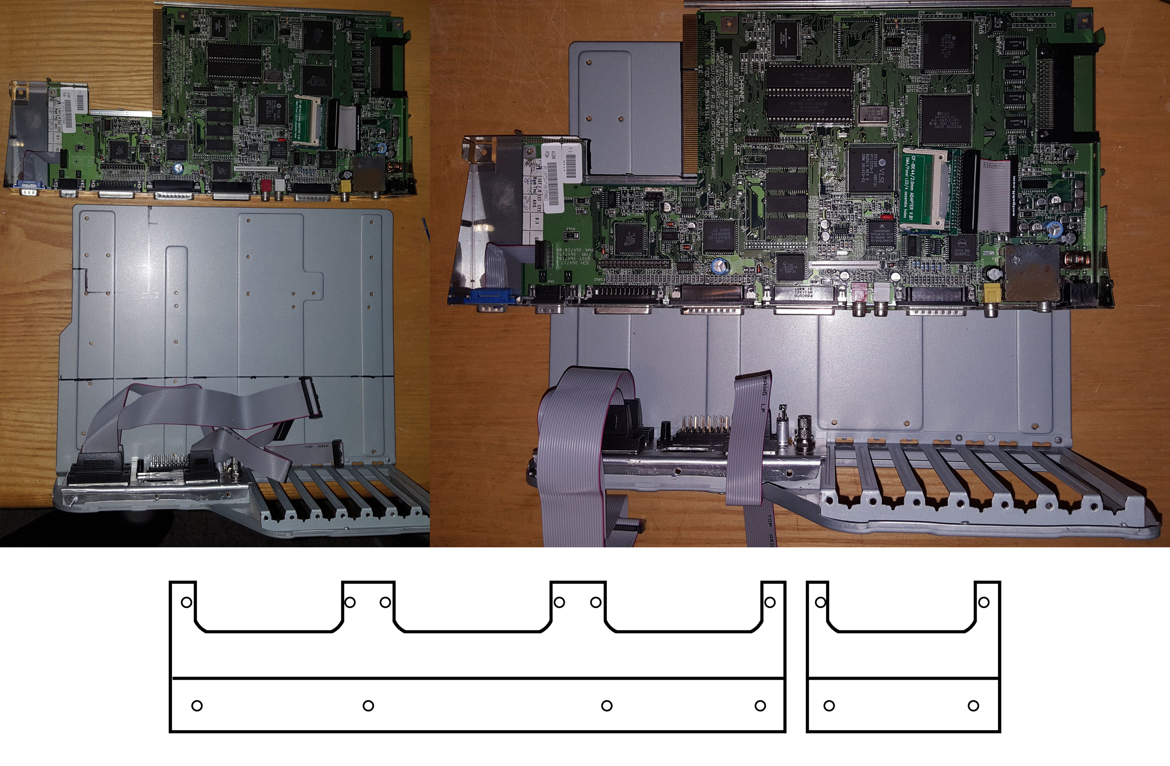
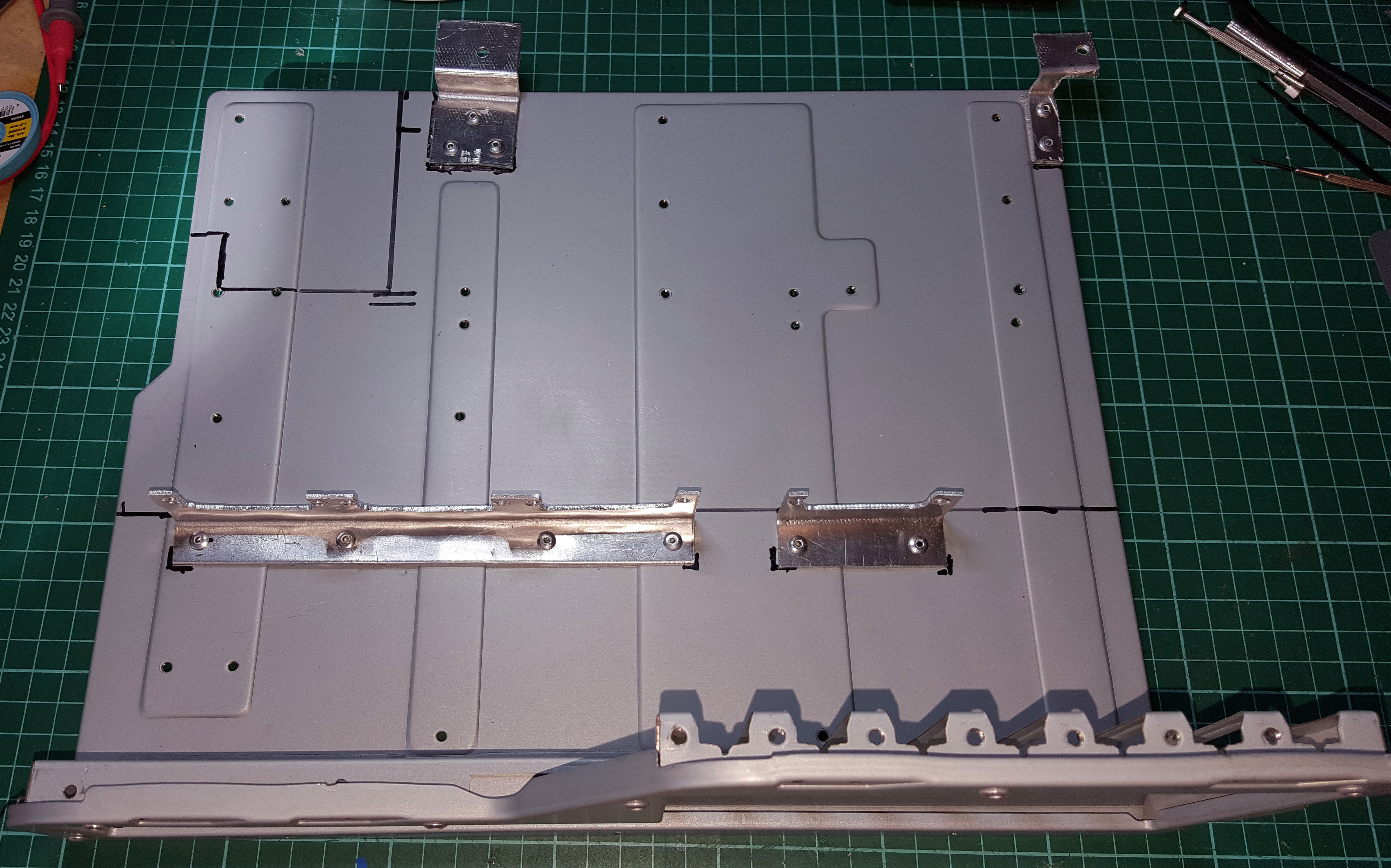 Now for some mounting brackets for the motherboard (cut from aluminium plate like the backplate)
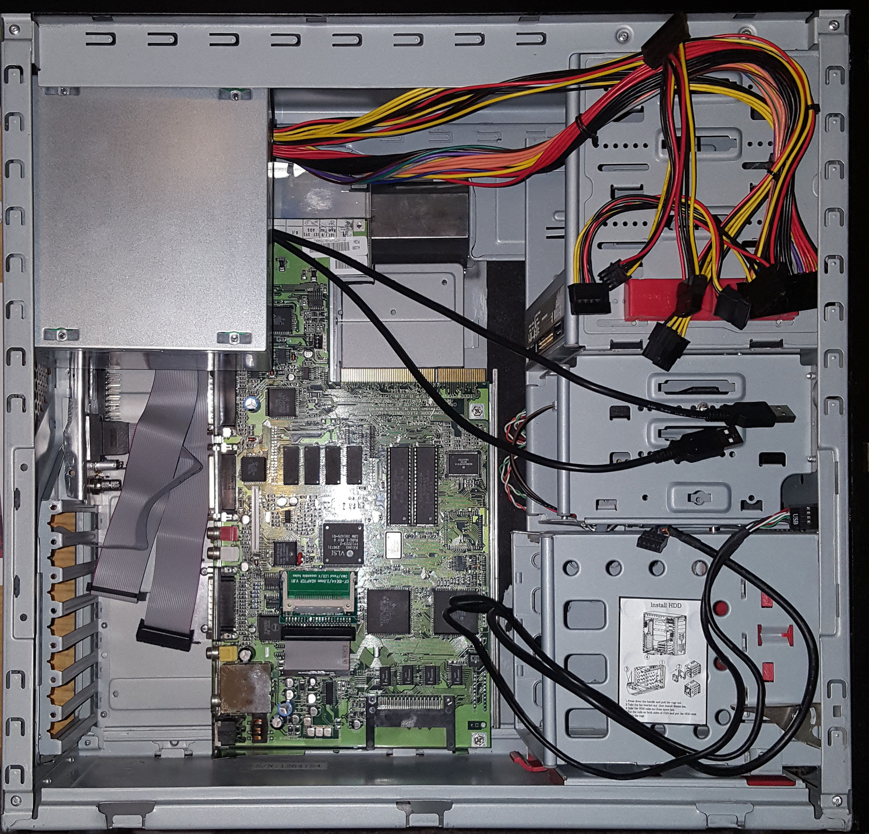 So far it looks real nice and neat on the inside. I’ll soon fix that 🙂
 More aluminium plate to cover the gaping hole at the top.
Those are not true USB’s, the top one can only handle a PS/2 compatible USB keyboard and the bottom is for the PS/2 compatible USB mouse previously mentioned. Later on I will probably add real USB’s to the front plugs via a daughterboard on the clock port.
A RJ45 coupling will server nicely for replicating the LAN plug for my PCMCIA network card.
An old working DVD drive and a Gotek SD floppy emulator (for DF0) already sits ready and waiting to be connected.